Mark's Cat Door
Mechanical Design
There are two doors: The outer door, which connects the garage to the outdoor world, then the inner door, which connects between the garage and the cats' "bedroom" (i.e, the bathroom). The outer door is more robust, with a large wooden door that moves up and down on rails:
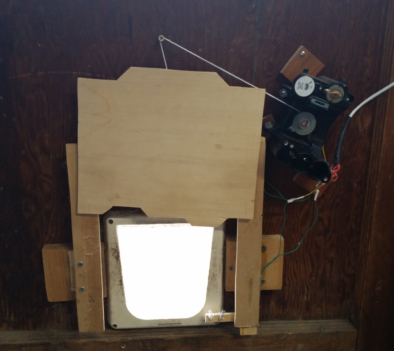
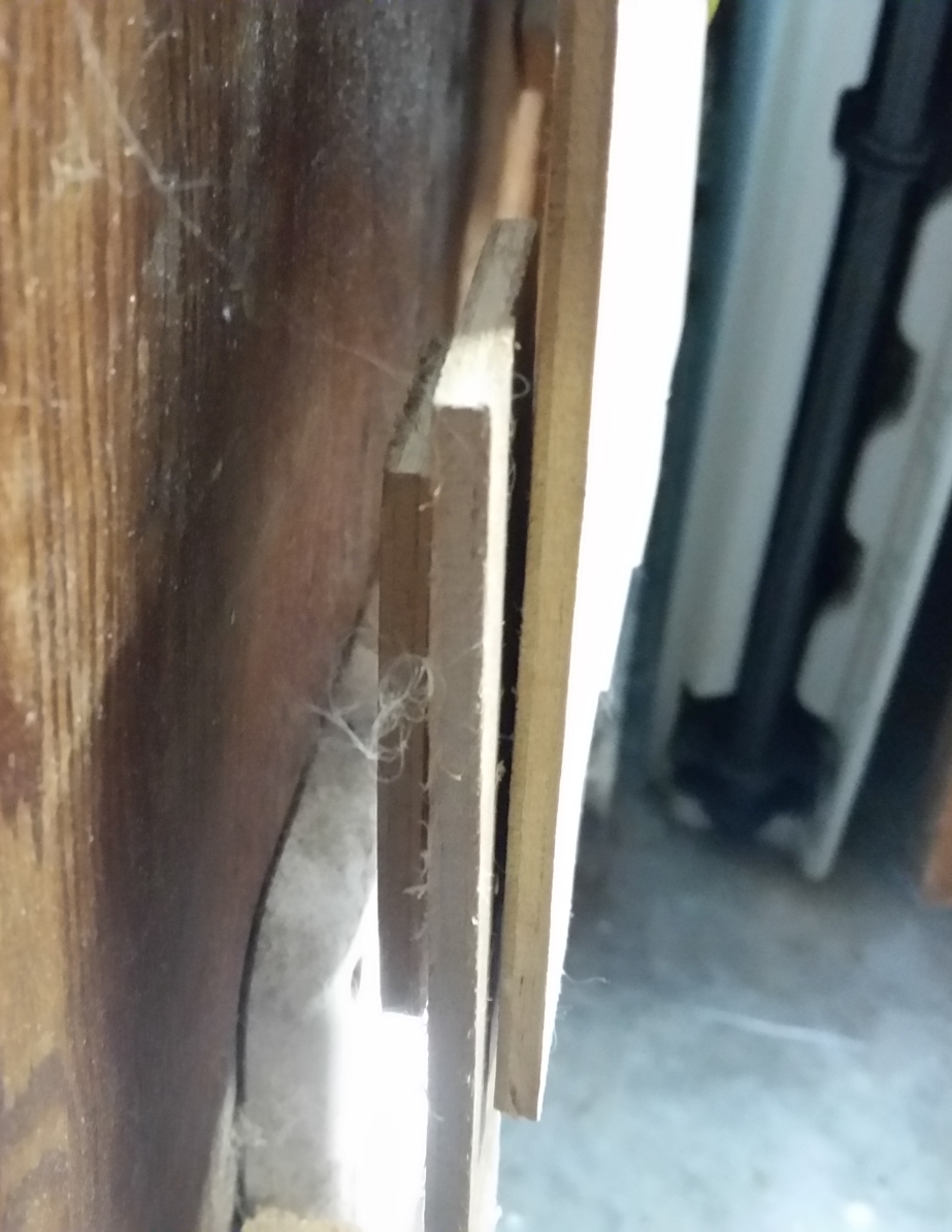
The door grips the rails from both sides to stay in place:
The motor is a geared DC motor salvaged from a Purell hand sanitizer dispenser. It has excellent torque and holding force for my purposes. At the top and bottom of the right-hand rail are springy contact sensors. An aluminum plate on the backside of the door (not visible) touches the springs together when the door is fully open or closed, notifying the logic board.
The inner door is simpler: A pencil that can swing down to block an old-fashioned cat door that already existed:
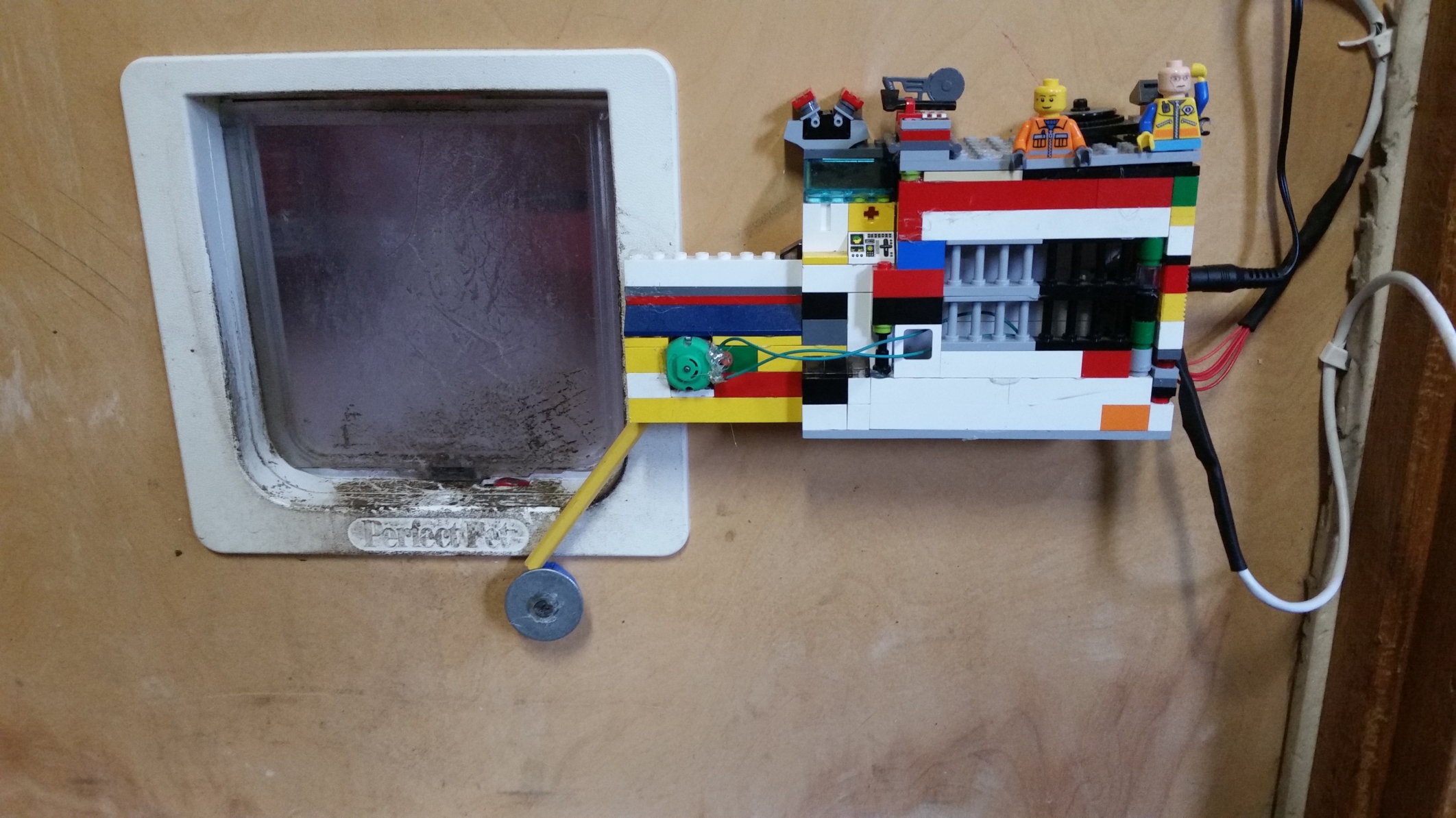
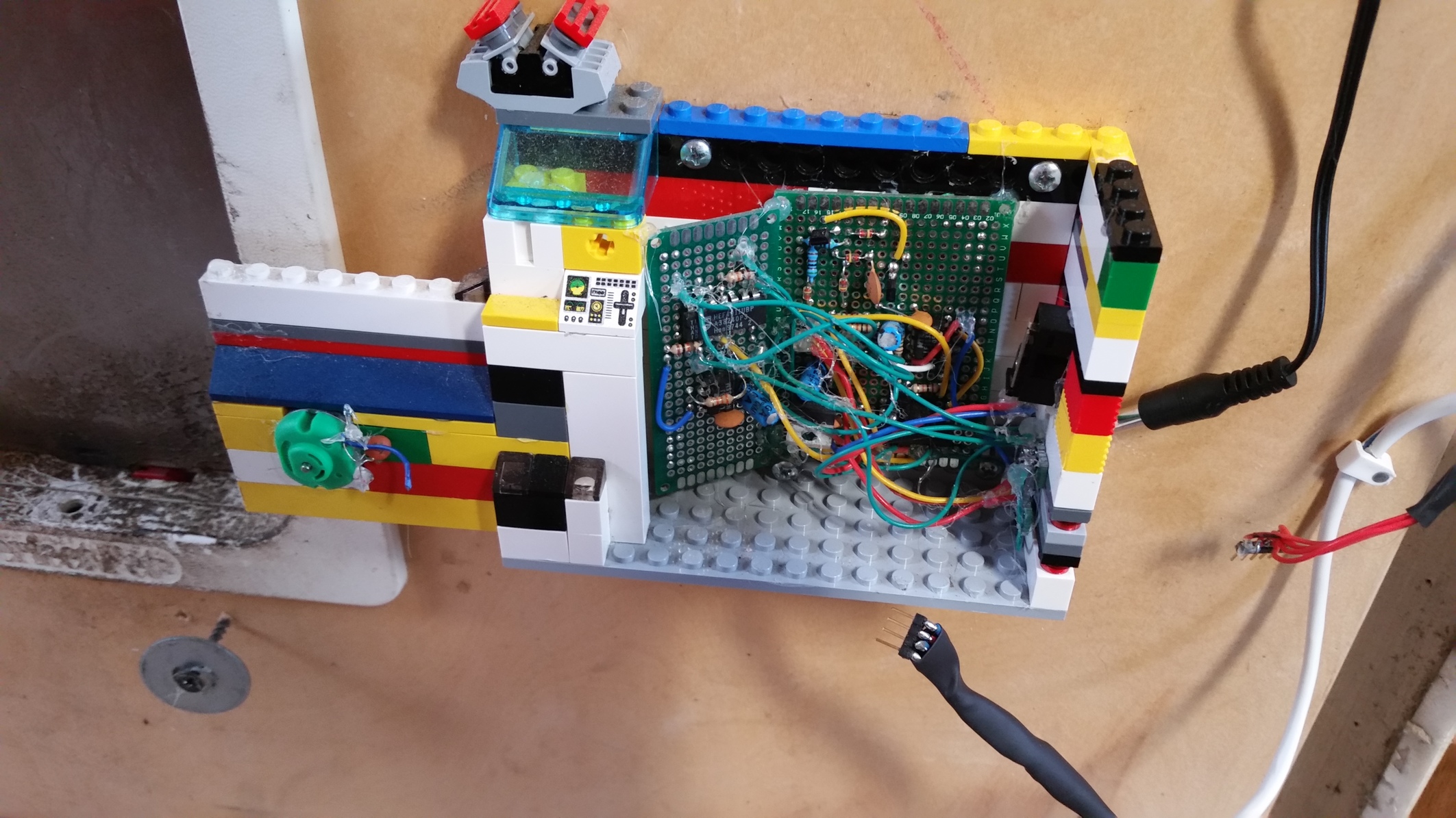
The pencil is light enough that I can swing it around using a standard toy motor without any gearing. It's attached to a Lego structure, where the main logic circuit board is housed.
I chose this design to allow one-way operation: At night, we like to let the cats come in, but then not go out again. In the one-way state, the outer door is opened and the inner door is closed. The cats are able to brush past the pencil in order to get into their bedroom, but cannot go back out because the pencil fully blocks the plastic door.
The control panel is an ON-OFF-ON switch plus multi-color LED:
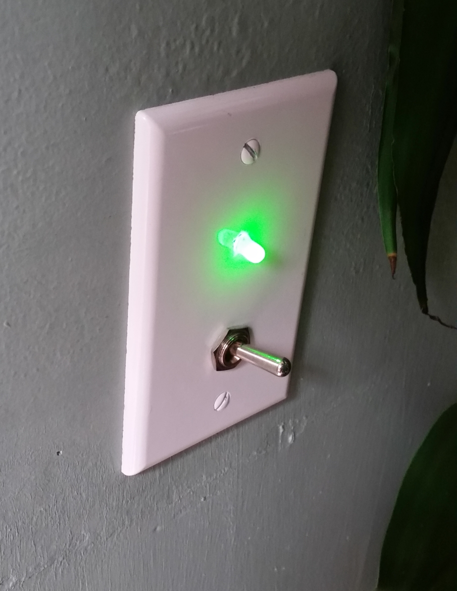
The color of the LED corresponds to the switch position (open = green, one-way = yellow, closed = red), and flashes when the door is in motion.
RJ-45 ethernet cables connect between the doors and the control panel.
Original Electronic Design
When I first built my cat door, I did it using so-called "standard logic" – i.e, logic gate ICs and discrete parts, with no programmable components. Here's how it looked, in all its glory:
I used a 4011 quad NAND gate to handle the outer door – when the switch is set to "open" but the "open" sensor is not activated, move the motor one direction, etc. The inner door was more complicated; there are no sensors, so I could not use any simple logic to determine when to rotate the pencil. Instead, I detected whenever the switch changed position, then turned on the motor for a fixed amount of time. I built a discrete XNOR gate (which really should be called NXOR) using some diodes, resistors, and transistors. I connected one input to the switch directly, then the other one through an RC delay. This way, the inputs were different, and therefore the output HIGH, whenever the switch changed position, because one input would change before the other.
The XNOR business never worked reliably; I built it with a fundamental misunderstanding of bipolar transistors. I also used large resistors (in the megaohms), which increases the likelihood that small current leakages and parasitic capacitances can mess with the circuit operation. At some point the XNOR gate stopped working entirely, and for a few months while I was busy with other projects, the inner cat door had to be opened and closed by hand.
Additionally, the outer door would sometimes get caught while lowering. The super simple outer door controller logic cannot account for this, so would keep rotating until the string gets spooled up in the opposite direction, raising the door again and continuing to run the motor once the door is fully raised, putting a lot of force on the top of the rail.
New Electronic Design
I'm very glad my first design was made of mainly discrete logic; It was my first major electronics project and it would not have been so fun to do it with a microcontroller. But, now that I actually want a working cat door, I have redesigned the control circuit board with an ATtiny84 microcontroller that can drive the inner door properly and handle edge cases with the outer door. The new board is on the right in this picture:
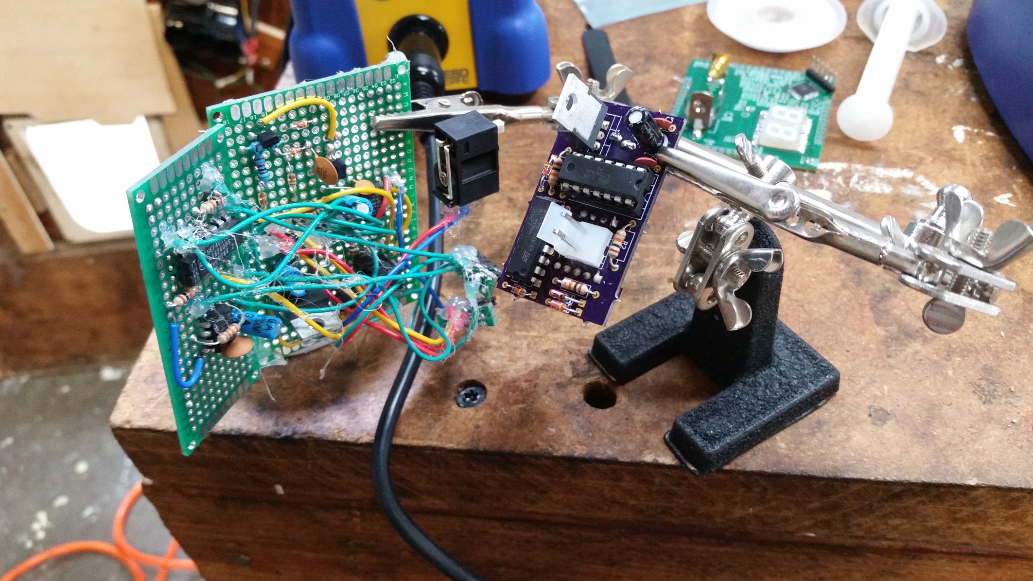
The only components are the ATtiny itself, an L293D dual H-bridge, a couple pulldown resistors, and two wired-OR gates (with diodes) to control the "enable" pins on the L293D without using extra pins on the ATtiny.
I handle all sorts of edge cases. If the outer door gets stuck on the way down, the string will spool around the motor in the wrong direction and eventually get stuck in the up position. My new design uses a timeout to detect this condition and run the motor the opposite direction until it's spooled normally again. Another issue was that the 9V 1A DC adapter I use does not provide enough current to reliably open the inner door and outer door simultaneously, so occasionally the pencil would not raise. My firmware ensures that only one motor is on at a time.
I've open sourced both the KiCAD files for the circuit board and the microcontroller firmware for this project: https://github.com/markasoftware/cat-door.